Introduction:
In today's technologically advanced world, software updates are crucial for optimal performance and security. This holds true for IDS (Integrated Diagnostic System) software installed on laptops to connect and perform diagnostics for Ford vehicles. Regularly updating IDS software ensures compatibility with the latest vehicle models and resolves any existing issues. In this article, we will guide you through the process of updating IDS software on your laptop to the latest version.
Why Update IDS Software:
Updating IDS software is essential for maintaining optimal security and performance for your laptop. With each update, the software becomes more stable and efficient, as previous errors are fixed. Additionally, updates often introduce new features and improvements to enhance diagnosis accuracy.
Steps to Update IDS Software:
Here are the steps to update your IDS software to the latest version:
1. Check for the Latest Version:
Begin by visiting the website of the software provider or contacting their customer support to determine the latest version of IDS software available.
2. Download the Latest Version:
Once you have the information about the latest version, download the software from the provider's website. Ensure that you download it from a trusted source.
3. Install the Software:
After the download is complete, follow the installation instructions provided by the software provider. Make sure to carefully read and understand each step to avoid any errors.
4. Launch and Update:
Once the installation is complete, launch the IDS software. It should prompt you to update to the latest version. Follow the on-screen instructions to complete the update process.
Compatibility:
Before updating IDS software, it's important to ensure compatibility with your laptop's operating system. IDS software is designed to work with Windows XP or Windows 7. If you have a different operating system, check with the software provider for compatibility options or updates.
Conclusion:
Updating IDS software on your laptop to the latest version is crucial for optimal performance and security. By following the steps outlined in this article, you can easily update your IDS software and ensure compatibility with the latest vehicle models. Remember to regularly check for updates to stay up-to-date with evolving automotive technology and enjoy an enhanced diagnostic experience.
Disclaimer: This article is intended for informational purposes only. The process of updating IDS software may vary depending on the specific software version and laptop configuration. It is recommended to consult the official documentation or contact the software provider for detailed instructions and support.
2023年11月30日星期四
How To Update IDS Software on Your Laptop to the Latest Version
2022年5月17日星期二
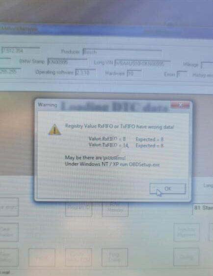
SVCI 2020 Registry Value RxFIFO or TxFIFO Have Wrong Data solution
Problem
The SVCI 2020
is failed to communicate with a new BMW E46 2001 GEN that has been
replaced recently. The warning “Registry value RxFIFO or TxFIFO have
wrong data! Maybe there are problems! Under Windows NT/XP run
OBDSetup.exe.” keeps coming out.
I’ve tried several times but was unable to clear the error. Any ideas?
Solution
Please follow the steps below, then re-connect the device to read fault codes again.
Step1. Open the SVCI 2020 installation directory.
Step2. Enter “C: Program File (x86)\Abrites Commander Software
List\Common2\” directory and copy BMW folder to “C: Program Files
(x86)\Abrites Commander Software List\Common\” directory
Hope this is helpful.
2022年4月16日星期六
How to change VCM2 serial number
I have figured out how to change the serial number of the Ford VCM 2 as well as enter test mode, and get a root shell on it.
You’ll need a microSD card for this to work.
1. Use IDS 86.
2. Recover your VCM2.
a. Describing how to recover is beyond the scope of this post. Search the forums for instructions.
b. After recovery your VCM2 should be at VCM2 FW version 2.1.1.5.
3. Wait about 90 seconds after the VCM2 beeps before proceeding. We are waiting for the SD card to be populated.
4. Unplug the VCM2 and eject the SD card.
5. Mount the SD card with a linux machine.
6. On the SD card open ‘apps/vci-diags/hwtest-scripts/self-test.sh’ for editing.
7. Add the following line to the file:
touch /etc/vci/config/testmode
8. Cleanly unmount the SD card and insert it back into the VCM2.
9. Plug the VCM2 unit into the computer and wait 90 seconds past beep before proceeding.
10. Launch IDS.
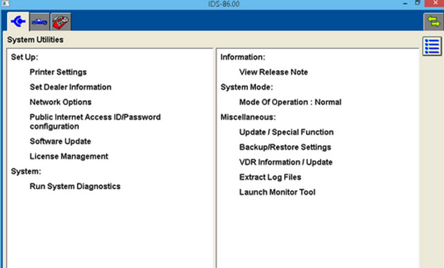
11. Go to system utilities
12.Select ‘Launch Monitor Tool’ and confirm on the pop up.
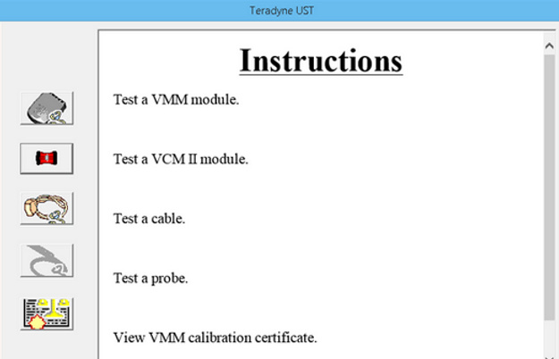
13. Select ‘Run System Diagnostics’ > ‘Next’ > ‘Test a VCM II Module’ > ‘Next’
14.Once the test completes unplug, wait a couple seconds, and then re-plug the VCM2 into the computer.
15. Wait about 15 seconds past when the VCM2 beeps and point your browser to http://192.168.171.2
You are now in the test mode web server.
a. To set a new serial number select ‘Set New Serial Number’ and proceed with serial number setting.
The default serial number is: 1211-31605352
b. To get a root shell Telnet to 192.168.171.2 you will be dropped to a root shell without providing login credentials.
c. To stay in testmode at next reboot select ‘Set Repair Test Mode’. This has to be done once per boot or you will have to go through this whole process to re-enable test mode.
Here Be Dragons:
To those who would go poking around, tread carefully. I accidentally ran cgi-bin/total-reflash and wiped my VCM2.
My bootloader was still intacted and available on pins 24 & 25 of the HDL26-PL-B connector.
2022年3月14日星期一
How to Install Software for Ford and Mazda
Firstly please prepare two laptops, one for software for Ford, the other is for Mazda. This is the instruction for the tool Ford
Ford IDS Software Free Download :
Ford_IDS V124: https://mega.nz/folder/6dwzgaJR#XW2q1xPdbgKV4XtZQqkB0w
Mzd_IDS V124: https://mega.nz/folder/iQp1UACZ#d4ey2cWHmaEMf9n2dTcTAQ
Ford_Mzd V124: https://mega.nz/folder/OV4RRC6B#seCWP6UCzOPWEDYlQxZ1iQ
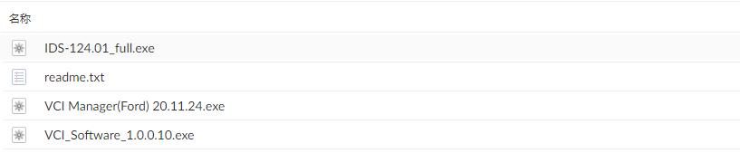
Here are the installation steps for Ford.
1. Install Ford IDS-124
2. Wait for the installation of Ford IDS – 124, and restart the computer
3. Install the Ford original VCI software_ 1.0.0.10.exe
4. Install VCI manager (Ford) 20.11.24 and Ford IDS driver
5. Wait for the VCI manager and Ford IDS driver installation to complete
6. Connect device and install IDS patch
7. Use IDSpatch to open IDs and start diagnosis.
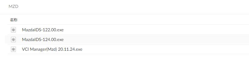
Here are the installation steps for Mazda.
1. Install Mazda IDS-124
2. Wait for the installation of Mazda IDS – 124, and restart the computer
3. Install VCI manager (Mazda) 20.11.24 and Mazda IDS driver
4. Wait for the VCI manager and Ford IDS driver installation to complete
5. Connect device and install IDS patch
6. Use IDSpatch to open IDs and start diagnosis.
2022年3月6日星期日
how to change the serial number of the Ford VCM 2
I have figured out how to change the serial number of the Ford VCM 2 as well as enter test mode, and get a root shell on it.
You’ll need a microSD card for this to work.
1. Use IDS 86.
2. Recover your VCM2.
a. Describing how to recover is beyond the scope of this post. Search the forums for instructions.
b. After recovery your VCM2 should be at VCM2 FW version 2.1.1.5.
3. Wait about 90 seconds after the VCM2 beeps before proceeding. We are waiting for the SD card to be populated.
4. Unplug the VCM2 and eject the SD card.
5. Mount the SD card with a linux machine.
6. On the SD card open ‘apps/vci-diags/hwtest-scripts/self-test.sh’ for editing.
7. Add the following line to the file:
touch /etc/vci/config/testmode
8. Cleanly unmount the SD card and insert it back into the VCM2.
9. Plug the VCM2 unit into the computer and wait 90 seconds past beep before proceeding.
10. Launch IDS.
11. Go to system utilities
12.Select ‘Launch Monitor Tool’ and confirm on the pop up.
13. Select ‘Run System Diagnostics’ > ‘Next’ > ‘Test a VCM II Module’ > ‘Next’
14.Once the test completes unplug, wait a couple seconds, and then re-plug the VCM2 into the computer.
15. Wait about 15 seconds past when the VCM2 beeps and point your browser to http://192.168.171.2
You are now in the test mode web server.
a. To set a new serial number select ‘Set New Serial Number’ and proceed with serial number setting.
The default serial number is: 1211-31605352
b. To get a root shell Telnet to 192.168.171.2 you will be dropped to a root shell without providing login credentials.
c. To stay in testmode at next reboot select ‘Set Repair Test Mode’.
This has to be done once per boot or you will have to go through this
whole process to re-enable test mode.
Here Be Dragons:
To those who would go poking around, tread carefully. I accidentally ran cgi-bin/total-reflash and wiped my VCM2.
My bootloader was still intacted and available on pins 24 & 25 of the HDL26-PL-B connector.
2022年2月27日星期日
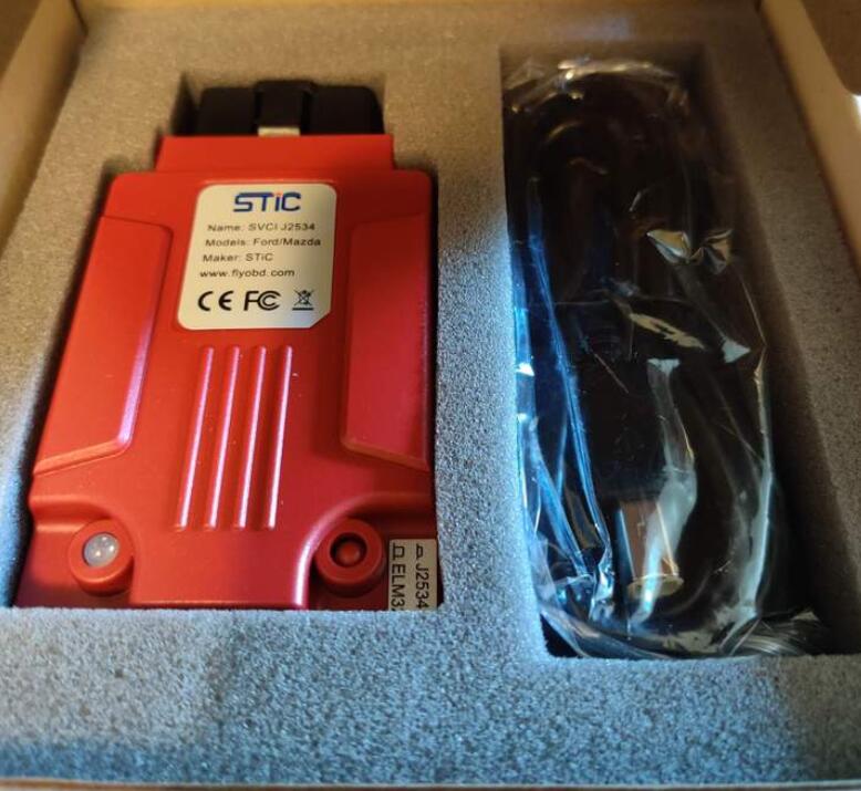
Free Download SVCI J2534 Ford IDS V125 Software & Patch
STIC SVCI J2534 Ford IDS software V125 has been tested and verified working without problem Obd2tool.com shares free download resources.
Software Operation System: Win7 64bit, Win 8, Win 10
SVCI J2534 ford QuickLoader V1.2.5 patch
https://mega.nz/file/fvpkxQAR#7Drt3vyEPSRGpbe4Tum5PzKvTH-5zbPJj6p4EFOLr2A
Free download Ford IDS 125
https://mega.nz/file/2ng0FajQ#n9Zf600-CvQtv48W2BToBaNqf9RK2KemJjHo63ZV4mI
SVCI J2534 VCI V1.0.0.0
https://mega.nz/#!anBG3CZa!SyersJzW3BA_FLFuBBK-hFU2JwGNvuPuWhxrT6QZWsk
No password!
SVCI J2534 Ford vs VCM II vs Other Ford J2534
| Function | SVCI J2534 | Genuine VCM II |
Other Ford J2534 | NOTE |
| Automatically startup without license | Yes | Need license | – | |
| Support online module programming | Yes | Yes | – | |
| Support online PATS/RKE learning | Yes | Yes | – | |
| Support SAE J1850 PWM 83.3K baud rate | Yes | Partly | – | |
| Support FEPS 18V programming voltage | Yes | Yes | Partly | |
| Support FEPS 5-20V adjustable voltage | Yes | Partly | – | |
| Support reading programming voltage | Yes | Partly | – | |
| Support EEC-V multiple items data logger | Yes | Partly | – | |
| Support PTEC multiple items data logger | Partly | Partly | Yes | MY 1994-2000 Ford |
| Support SAE J1850 module programming | Partly | – | – | MY 2000-2006 Ford |
| Support power balance performance test | Partly | Partly | – | MY 1995-2006 Ford |
| Support CANBUS module programming | Partly | Partly | Partly | MY1995-2006 Ford |
| Support online software update | Yes | – | – | |
| Calculate incode pre-2010 for free | Yes | – | – |
SVCI has been tested working with FJDS, FDRS programs for new Fords.
SVCI has fixed J1850 PWM protocol module programming bugs in Feb. 2021. Users can set reprogramming voltage to 18V on PIN 13 and do reprogramming for Ford J1850 PWM vehicle.
SVCI J2534 Ford J1850 PWM Module Reprogramming Guide
Guide to install SVCI J2534 ford software:
Step 1: Download IDSFord software
Step 2: Download SVCI-J2534-for-ford patch software
Step 3: Download IDS-VCI (Ford) software
Step 4: install software directly that downloads
2022年2月20日星期日
VCM2 Only see 2003 Lincoln Town in HS Mode
Problem:
2003 Lincoln Town Car Signature with Park Aid
Interface OHP ELMconfig USB with manual HS//MS switch
Connects successfully in HS mode and I can see DDM,DSM LCM, ATC,ABS, PATS and other modules – but not PAM.
Suggestion:
The ISO9141 Protocol has been supported by Both Forscan And ELM327 based adaptors since the beginning versions. HS/MS switch must be in the HS Can position for these early SCP/PWM and ISO equipped Vehicles. MSCan Position will have no connection.
WDS and NGS are the obsolete Ford Diagnostic software and hardware that were replaced by IDS and the VCM and VCM 2
Your Lincoln May have a DLC UBP pin 3 but as far as I know the Cars never had a UBP network or anything connected to it as it was mostly used in the Trucks and SUV’s. There would be about 3 to 5 volts positive to Ground if anything is connected to Pin number 3. Another member on this forum had checked his Lincoln and the 3 pin was there but it was dead.
If the PAM module was responding to Forscan through the adaptor, it should have shown up in the ISO network tree along with any other modules that are likely on that same network(The overhead consol display that the PAM warning appears on would have to be on that network) and also appeared in the vehicle configuration list.
If it is not showing up there then you will need to gain
access(Remove trim panels and such like. Check manual for module
location and connector views) to the display module connector and the
PAM module connector to check if the positive voltage is present in the
PAM module connector and the ground connection out of the connector has
continuity.
Then continuity from the PAM module connector to each of the sensors connectors in rear bumper will be next!
If the module is receiving 12 V+ Power and is grounded( A working module should be showing in the network list with DTC’s if these and ISO wiring are good) and sensor wiring and connectors check out then the module communication wires from the PAM module Connector to the Display’s connector and to the DLC Pin number 7 will be the next to check as the Display gets the PAM signal from the PAM module over the ISO network.
If You say you have Service manual then You are about to make good use of it!
It should have wiring and connector Diagrams and a Pin Point flow chart in it!
If the PAM module is receiving 12V+ and has a ground connection the
sensor connections check out(sensors and connectors are prone to
moisture and corrosion) and the Display and PAM module’s ISO Connection
to No7 DLC Pin all check out then you have a PAM module that has
probably died!
It does Happen!
Good luck! Hope this is of some help?
Question:
Thanks for the feedback. The manuals are helpful except, in this case a bit confusing. In the Module Comunications Network section it says the PAM is on the UBP network and refers me to the Parking Aid section in the same manual, but in that section it clearly says the PAM is on the ISO 9141 network as I mentioned above. I do see the Restraint Control Module (RCM) show up so I guess I do have access to ISO9141.
As for truck vs car – I have noticed the Panther platform (Crown Vic, Grand Marquis, Town Car) seems to “borrow” a lot of components from the truck lines, esp. Explorer. Maybe it’s the similarities in construction and drive line.
Answer:
You are not alone in the confusion you are experiencing! I ran into this same predicament with my 03 Expedition. The Wiring manual I have shows the PAM in Module communications on the UBP (Violet Wire) network but Forscan reads it on the ISO(Light Blue/White wire) network and the Service manual says PAM is on the UBP network.
It seems that even Ford is confused about this!
If your TC has Climate Controlled Seats and you are not seeing them on the network list they may also be on the UPB network as are mine in the Expy.
If Pin 3 shows any voltage(5 V+ Key on in my Expy) to ground (Pin 4 or 5 in the DLC) you may have a UPB network and PAM may be on it in this case and that is only available with A VCM2 in Forscan. Never have tried with anything else except VCX Nano and that was an exercise in futility. Never got it to connect at all to either of these “Old Guys”! Had to go for a VCM2 Clone (Used it to help the team get UBP support working back in Version 2.3.09) and it has been good so far! Getting hard to find a good one of those unfortunately.
Only other way to tell, and you may be going in there in any case, is to to gain access to the PAM Module connector and see what wire colours are going into the Module Communications pin. Violet likely means UBP, Light Blue/White means ISO, at least it is in the two trucks (03 Expy and 05 F150) I have here, but your TC wiring Diagram may differ!
Question:
Yea “FORD Engineered” is sometimes a complement and sometimes a curse..